Construction Analysis of Column type Load Cell Elastic Element
The elastic element of column type load cell is normal stress cylindrical and columnar elastic elements. The normal stress cylindrical and columnar elastic elements can be divided into the single-column type, single-cylinder type and multicolumn type. The single-column type features the cylindric, columnar, truncated columnar, and truncated cylindric structure. Upon customer requires, other structures, including square column, square drum, prism, and edge drum, can also be adopted. Structures, including multi-cylindrical, multi-drum, and three-square-column, four-square-column, three-square-drum and four-square-drum, dominate.
1. Structural and mechanical analysis of single-column and single-drum elastic elements
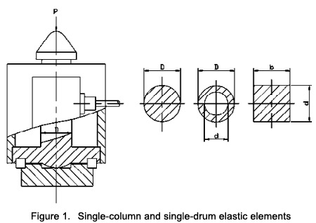
The load cell structure composed of normal stress single-column and single-drum elastic elements is shown in Fig. 1.

The normal stress single-column and single-cylinder elastic elements have a simple and compact structure. The geometric shapes, including cylinder, column, square column, and square cylinder, can easily achieve a high precision of dimensions and shape after processing. The elastic elements have a high stiffness, fixed frequency and fast dynamic response. It can realize integrated design of elastic elements and swing posts. In other words, elastic elements and double spherical swing posts are integrated into one whole structure. Its elastic elements can also help automatically achieve self-alignment and self-spacing of the double-spherical swing post, decrease the loader height and improve stability. Its defects include poor fixed linearity, and below are causes of nonlinear errors:
1.1 Nonlinear errors of bridge circuits:
The cylindric elastic element output and strain relational expression can be deducted as below:
S=Uo/Ui=1.28ε(1-0.72ε)
It can be easily seen that the output and strain constitute a nonlinear relationship. Only when ε reaches adequate hours will the output and strain constitute the linear relationship, which can be written as below:
S=Uo/Ui=1.28ε
Experiment carried out by the German sensor scholar Reynard suggests that when the axial direction of the cylindric elastic elements is changed by every 100με, the bridge will generate around nonlinear error of around 0.007%.
1.2 Nonlinear errors caused by sectional area changes
Sectional area changes of elastic elements after being loaded will generate the Poisson's ratio effect and elasticity modulus effect. When cylindric elastic elements suffer compression elements, the cross-sectional area increases, and the stiffness strengthens continuously, outputting the degressive parabola, which is smaller than the linear value. When the cylindric elastic elements are suffering pulling load, the cross-section decreases, and the stiffness continuously weakens, thus outputting the progressive parabola whose output is larger than the linear value.
Influence of the elastic modulus effect: When the cylindric elastic elements are suffering compression load, the elasticity modulus, E, will increase slightly, and the output will be on a decreasing trend, thus enhancing the area effect. When the cylindric elastic elements are suffering pulling load, the elasticity modulus, E, will decrease slightly, and the output will be on a progressively increasing trend, thus aggravating the area effect.
Affected by the Poisson's ratio, μ, the difference between the axial strain and the radial strain will exert a huge influence on the output value. In order to improve the sensitivity, S, it is necessary to enlarge the axial strain, ε, and increase of ε will inevitably generate non-constant factors for the P - ε function, which will then deepen the nonlinear error. The nonlinear error caused by deduction of the cross-sectional area can be deduced as below:
Receiving the tension load:
Δ2=+0.56ε
Receiving the compression load:
Δ2=-0.56ε
Experiment suggests that when the axial direction of the cylindric elastic elements is changed by every 100με, the bridge will generate around nonlinear error of around 0.003%.
1.3 Nonlinear errors caused by resistance strain gauge
Relative changes of resistance strain gauge and strain ε constitute a linear relationship within certain strain scope. The nonlinear error can be given by the following equation:
Δ3=(K-1)ε/2!
IfΔ3 is controlled within 0.05%, then:
ε=2Δ3/(K-1)=2*0.0005/(2-1)=0.001=1000*10-6
In order to give full play characteristics of cylindric and columnar elastic elements and to ensure a high accuracy rate, linear compensation is necessary.
It is easy to see that the fixed defects of the single-cylinder elastic element structure are prominent. During the use process, it is influenced by the eccentric load, lateral load, and moment along the central axis direction of the cylinder, the cylindric elastic elements will experience irregular deformation, which will impair accuracy, shorten service life and even damage the load cell. The application precision of the single-column load cell on the balancer is lower than the precision measured by the force standard machine. This is because the deformation of the sales leads to skewing of the load cell, which cannot avoid being influenced by eccentricity and lateral load. A solution is that elastic elements adopt the double-spherical (or swing-post) structure, which is actually the lengthened steel ball, to ensure the external load to function on the center of the load cell more precisely, and ensure its transmission along the central axis of the cylinder. Facts prove that an effective way to cope with the fixed defect is to adopt the multi-column elastic elements.
2. Structural and mechanical analysis of multi-column elastic elements
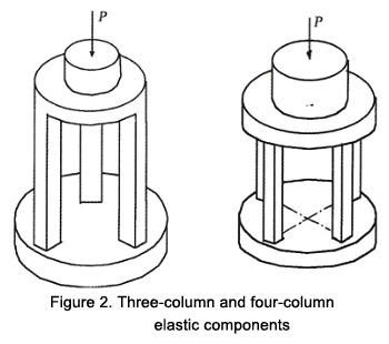
Multi-column elastic elements can be divided into the integrated multi-column one and the assembled multi-column one. The integrated three-column and four-column elastic elements are widely used. It is a section of cylindric workblank which just allows strengthening but no thickening of piers, and an integrated structure which is processed once for all in the CNC machining center. Every column of the three-column type and the four-column type is symmetrically and evenly distributed along the circular pedestal of the elastic elements. The column features a square cross-section. The spherical surface or the spherical bowl is processed at the center of the top plate for the convenience of introducing the external load. American scholars think that the multi-column elastic elements are a breakthrough of the column-type load cell design, manufacturing and compensation (integrated circuit linear compensation) technology. The structure of the integrated three-column and four-column elastic elements is shown in Fig. 2, respectively.

The integrated three-column and four-column elastic element structure can not only make up the fatal defects of the single-column elastic element structure, including weak resistance against eccentricity and lateral loading, but also essentially improve the output sensitivity, measurement precision and application characteristics of the load cell. Since the integrated three-column and four-column elastic element structure can increase the spherical radius of the loading part, the deformation degree of the loading spherical ball head under the large load and impact load is significantly reduced, and the static and dynamic application characteristics of the load cell are significantly improved. Under the effect of the eccentric load and lateral load, every column of the integrated three-column and four-column elastic element structure receives different forces, which can be used to counteract the moment generated by the eccentric load and lateral load. This can significantly reduce the irregular deformation caused by elastic elements.
2.1 Characteristics of the integrated three-column and four-column elastic elements
Structural characteristics of the integrated three-column and four-column elastic elements include a large force value and a low appearance. The resistance against lateral load and eccentric load is improved. The resistance of the single-column structure against the load is just around 5% of the rated load, while the figure for the integrated three-column structure is 30% and 50% for the integrated four-column structure. The bearing pressure head radius is increased, the pressure head deformation is reduced and the static and dynamic working characteristics are improved under large load and impact load. There is no need to design the complex protection shell. To paste or welder flat diaphragms between columns is a feasible way for sealing. The structural design is simple, and one just needs to calculate the load to be borne by the single column so as to meet the requirement of the output sensitivity.
2.2 Analysis of eccentric load resistance characteristics of the integrated four-column elastic elements
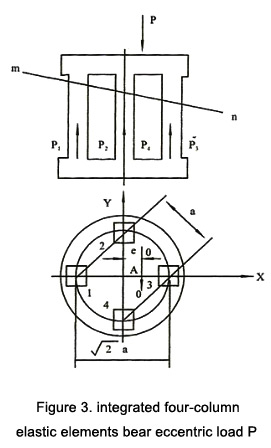
The schematic diagram of the eccentric load, P, imposed on the integrated four-column elastic elements is shown in figure 3.
Assume that the eccentric distance of P along the X-axis is e. After deformation, the stiff top plate of elastic elements is located at the position m—n, so the load imposed on Column 2 and Column 4 is equal to the mean of the load imposed on Column 1 and Column 3.
Hence, P2=P4
2P2=P1+P3 (1)
2P2+P1+P3= P (2)
Combine Eq. (1) and Eq. (2), and the following equation can be obtained:
2P2=P1+P3=P/2 (3)
Choose the O—O axis passing Point A and parallel to Y-axis, and the moment of this axis is:
P1(1.414a+e)+2P2e=P3(1.414A-e)
P1(1.414a/2+e)+Pe/2=P3(1.414a/2-e)
Combine Eq. (3) and Eq. (4) to obtain Eq. (5):
P1=P(0.25-e/1.414), P2=P/4, P3=P(0.25+e/1.414) (5)
Calculate the eccentric load resistance with the square cross-sectional area (side b=18mm; column L=80mm) four-column load cell (P = 20000kg, bottom radius R1 = 40mm, and the radius of center circle in every column).
Calculate the distance between two columns, a = 39mm. If the eccentric distance of the load P along the X axis is e = 3mm, then:
P3=P(0.25+e/1.414a)=20000(0.25+3/1.414*39)=6088kg
Based on computing results, the overload of the third column is 1,088kg, which is 21.8% of the rated load, 5,000kg.
If the eccentric distance, e=4mm, then:
P3=P(0.25+E/1.414a)=20000(0.25+4/1.414*39)=6450kg
The overload of the third column is 1,450kg, which is 29% of the rated load, 5,000g. In fact, the integrated four-column load cell can overload by 50%, which is P3 = 7,500kg. At the moment, the pressure stress is σ = 23.1kg/mm2.
2.3 Low capacity single-column elastic element structure
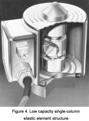
0.5t to 10t single-column elastic element has a low capacity, so its diameter is inevitably small. Not only does the single-column elastic element have a poor stiffness and poor stability but also it is unsuitable for the pasting resistance strain gauge. Therefore, the blind-hole compression structure is adopted. In other words, two blind holes are processed internally on two sides of the central position of the cylindric elastic element. Through control of the horizontal cross-sectional wall hole dimensions, the axial stress and the horizontal stress on the blind hole plate are close to each other, which can effectively improve the fixed linearity. The load cell made up of the small-gauge single-column elastic elements is shown in Fig. 4 below:

1. Structural and mechanical analysis of single-column and single-drum elastic elements
The load cell structure composed of normal stress single-column and single-drum elastic elements is shown in Fig. 1.

The normal stress single-column and single-cylinder elastic elements have a simple and compact structure. The geometric shapes, including cylinder, column, square column, and square cylinder, can easily achieve a high precision of dimensions and shape after processing. The elastic elements have a high stiffness, fixed frequency and fast dynamic response. It can realize integrated design of elastic elements and swing posts. In other words, elastic elements and double spherical swing posts are integrated into one whole structure. Its elastic elements can also help automatically achieve self-alignment and self-spacing of the double-spherical swing post, decrease the loader height and improve stability. Its defects include poor fixed linearity, and below are causes of nonlinear errors:
1.1 Nonlinear errors of bridge circuits:
The cylindric elastic element output and strain relational expression can be deducted as below:
S=Uo/Ui=1.28ε(1-0.72ε)
It can be easily seen that the output and strain constitute a nonlinear relationship. Only when ε reaches adequate hours will the output and strain constitute the linear relationship, which can be written as below:
S=Uo/Ui=1.28ε
Experiment carried out by the German sensor scholar Reynard suggests that when the axial direction of the cylindric elastic elements is changed by every 100με, the bridge will generate around nonlinear error of around 0.007%.
1.2 Nonlinear errors caused by sectional area changes
Sectional area changes of elastic elements after being loaded will generate the Poisson's ratio effect and elasticity modulus effect. When cylindric elastic elements suffer compression elements, the cross-sectional area increases, and the stiffness strengthens continuously, outputting the degressive parabola, which is smaller than the linear value. When the cylindric elastic elements are suffering pulling load, the cross-section decreases, and the stiffness continuously weakens, thus outputting the progressive parabola whose output is larger than the linear value.
Influence of the elastic modulus effect: When the cylindric elastic elements are suffering compression load, the elasticity modulus, E, will increase slightly, and the output will be on a decreasing trend, thus enhancing the area effect. When the cylindric elastic elements are suffering pulling load, the elasticity modulus, E, will decrease slightly, and the output will be on a progressively increasing trend, thus aggravating the area effect.
Affected by the Poisson's ratio, μ, the difference between the axial strain and the radial strain will exert a huge influence on the output value. In order to improve the sensitivity, S, it is necessary to enlarge the axial strain, ε, and increase of ε will inevitably generate non-constant factors for the P - ε function, which will then deepen the nonlinear error. The nonlinear error caused by deduction of the cross-sectional area can be deduced as below:
Receiving the tension load:
Δ2=+0.56ε
Receiving the compression load:
Δ2=-0.56ε
Experiment suggests that when the axial direction of the cylindric elastic elements is changed by every 100με, the bridge will generate around nonlinear error of around 0.003%.
1.3 Nonlinear errors caused by resistance strain gauge
Relative changes of resistance strain gauge and strain ε constitute a linear relationship within certain strain scope. The nonlinear error can be given by the following equation:
Δ3=(K-1)ε/2!
IfΔ3 is controlled within 0.05%, then:
ε=2Δ3/(K-1)=2*0.0005/(2-1)=0.001=1000*10-6
In order to give full play characteristics of cylindric and columnar elastic elements and to ensure a high accuracy rate, linear compensation is necessary.
It is easy to see that the fixed defects of the single-cylinder elastic element structure are prominent. During the use process, it is influenced by the eccentric load, lateral load, and moment along the central axis direction of the cylinder, the cylindric elastic elements will experience irregular deformation, which will impair accuracy, shorten service life and even damage the load cell. The application precision of the single-column load cell on the balancer is lower than the precision measured by the force standard machine. This is because the deformation of the sales leads to skewing of the load cell, which cannot avoid being influenced by eccentricity and lateral load. A solution is that elastic elements adopt the double-spherical (or swing-post) structure, which is actually the lengthened steel ball, to ensure the external load to function on the center of the load cell more precisely, and ensure its transmission along the central axis of the cylinder. Facts prove that an effective way to cope with the fixed defect is to adopt the multi-column elastic elements.
2. Structural and mechanical analysis of multi-column elastic elements
Multi-column elastic elements can be divided into the integrated multi-column one and the assembled multi-column one. The integrated three-column and four-column elastic elements are widely used. It is a section of cylindric workblank which just allows strengthening but no thickening of piers, and an integrated structure which is processed once for all in the CNC machining center. Every column of the three-column type and the four-column type is symmetrically and evenly distributed along the circular pedestal of the elastic elements. The column features a square cross-section. The spherical surface or the spherical bowl is processed at the center of the top plate for the convenience of introducing the external load. American scholars think that the multi-column elastic elements are a breakthrough of the column-type load cell design, manufacturing and compensation (integrated circuit linear compensation) technology. The structure of the integrated three-column and four-column elastic elements is shown in Fig. 2, respectively.

The integrated three-column and four-column elastic element structure can not only make up the fatal defects of the single-column elastic element structure, including weak resistance against eccentricity and lateral loading, but also essentially improve the output sensitivity, measurement precision and application characteristics of the load cell. Since the integrated three-column and four-column elastic element structure can increase the spherical radius of the loading part, the deformation degree of the loading spherical ball head under the large load and impact load is significantly reduced, and the static and dynamic application characteristics of the load cell are significantly improved. Under the effect of the eccentric load and lateral load, every column of the integrated three-column and four-column elastic element structure receives different forces, which can be used to counteract the moment generated by the eccentric load and lateral load. This can significantly reduce the irregular deformation caused by elastic elements.
2.1 Characteristics of the integrated three-column and four-column elastic elements
Structural characteristics of the integrated three-column and four-column elastic elements include a large force value and a low appearance. The resistance against lateral load and eccentric load is improved. The resistance of the single-column structure against the load is just around 5% of the rated load, while the figure for the integrated three-column structure is 30% and 50% for the integrated four-column structure. The bearing pressure head radius is increased, the pressure head deformation is reduced and the static and dynamic working characteristics are improved under large load and impact load. There is no need to design the complex protection shell. To paste or welder flat diaphragms between columns is a feasible way for sealing. The structural design is simple, and one just needs to calculate the load to be borne by the single column so as to meet the requirement of the output sensitivity.
2.2 Analysis of eccentric load resistance characteristics of the integrated four-column elastic elements
The schematic diagram of the eccentric load, P, imposed on the integrated four-column elastic elements is shown in figure 3.

Assume that the eccentric distance of P along the X-axis is e. After deformation, the stiff top plate of elastic elements is located at the position m—n, so the load imposed on Column 2 and Column 4 is equal to the mean of the load imposed on Column 1 and Column 3.
Hence, P2=P4
2P2=P1+P3 (1)
2P2+P1+P3= P (2)
Combine Eq. (1) and Eq. (2), and the following equation can be obtained:
2P2=P1+P3=P/2 (3)
Choose the O—O axis passing Point A and parallel to Y-axis, and the moment of this axis is:
P1(1.414a+e)+2P2e=P3(1.414A-e)
P1(1.414a/2+e)+Pe/2=P3(1.414a/2-e)
Combine Eq. (3) and Eq. (4) to obtain Eq. (5):
P1=P(0.25-e/1.414), P2=P/4, P3=P(0.25+e/1.414) (5)
Calculate the eccentric load resistance with the square cross-sectional area (side b=18mm; column L=80mm) four-column load cell (P = 20000kg, bottom radius R1 = 40mm, and the radius of center circle in every column).
Calculate the distance between two columns, a = 39mm. If the eccentric distance of the load P along the X axis is e = 3mm, then:
P3=P(0.25+e/1.414a)=20000(0.25+3/1.414*39)=6088kg
Based on computing results, the overload of the third column is 1,088kg, which is 21.8% of the rated load, 5,000kg.
If the eccentric distance, e=4mm, then:
P3=P(0.25+E/1.414a)=20000(0.25+4/1.414*39)=6450kg
The overload of the third column is 1,450kg, which is 29% of the rated load, 5,000g. In fact, the integrated four-column load cell can overload by 50%, which is P3 = 7,500kg. At the moment, the pressure stress is σ = 23.1kg/mm2.
2.3 Low capacity single-column elastic element structure
0.5t to 10t single-column elastic element has a low capacity, so its diameter is inevitably small. Not only does the single-column elastic element have a poor stiffness and poor stability but also it is unsuitable for the pasting resistance strain gauge. Therefore, the blind-hole compression structure is adopted. In other words, two blind holes are processed internally on two sides of the central position of the cylindric elastic element. Through control of the horizontal cross-sectional wall hole dimensions, the axial stress and the horizontal stress on the blind hole plate are close to each other, which can effectively improve the fixed linearity. The load cell made up of the small-gauge single-column elastic elements is shown in Fig. 4 below:


